Split3r GETTING STARTED

This guide (best viewed on a computer) walks you through your first setup and cut: installing the app, loading an STL, choosing a printer profile, and exporting split parts ready for print. We keep steps short and practical, with screenshots and minimal prerequisites.


Before you begin, download the latest Split3r build, and have a sample model (STL/OBJ) ready.


INSTALLATION

INSTALLATION

Split3r is available for Windows, macOS and Linux.


Windows: run the installer; it installs by default to C:\Program Files\Split3r_1.5.0 b4\. You can keep previous versions installed side by side.

macOS (Apple Silicon): open the signed, notarized DMG and drag Split3r into Applications. It launches normally, with no extra step.

Linux: download the AppImage, make it executable, and run it.

SOFTWARE ACTIVATION

Launch Split3r to open the activation window automatically, or open it via Help > Registration. Enter your email and name exactly as provided in the activation email (case sensitive), then click Validate.


If activation fails:

  • Check that your firewall/antivirus isn't blocking Split3r.
  • Make sure your computer's date and time are correct; enable automatic time sync.
  • If you use a VPN, try disabling it (it should work with VPN, but just in case of).
  • If it still fails, visit whatismyip.com, take a screenshot, note the exact date/time, and email it to support@split3r.com.

QUICK TEST

Windows : The Lambo demo project is installed with Split3r.

From Split3r, open Documents\Split3r\Workzones\Lambo\lambo.s3r.

Without changing any setting, click PRE-SPLIT, then SPLIT. After the calculation, the split parts appear.

Press E to explode and T to tighten the model.


macOS / Linux : The demo project isn't bundled with the DMG or AppImage.

Download the Lambo demo Workzone here: https://www.split3r.com/download/lambo.zip

Unzip it anywhere, then in Split3r open the lambo.s3r it contains.

Without changing any setting, click PRE-SPLIT, then SPLIT, and press E / T to explode and tighten.


DARK/LIGHT DISPLAY

You can switch between Dark and Light modes via Project > Toggle Theme in the main menu.


4 x MODES


Split3r is organized around four main working modes that structure your workflow from start to finish.
Use them in sequence :
PREPARE > PRE-SPLIT > SPLIT > EXPLODE, to move from model preparation to plane setup and final result review.

PREPARE

: Import and prepare your model (repair, scale, shell, cut some areas) inside a Workzone. The Active file here is the one used for the next steps.

PRE-SPLIT

: Position and adjust the cutting planes, use hotkeys and X/Y/Z controls to fine-tune the split configuration or use mouse drag to adjust position.

SPLIT

 : is the operation that runs after PRE-SPLIT and before you review results in EXPLODE. It takes the Active file and your current plane configuration, computes the partitions, and writes the output to a new results folde

EXPLODE

: Inspect, filter, and organize the resulting parts, manage visibility and bulk actions from the parts tree.

If you discover an issue, e.g., mispositioned cutting planes or very small parts that could have been avoided, switch back to PRE-SPLIT, adjust the planes’ positions and sizes, then run SPLIT again.


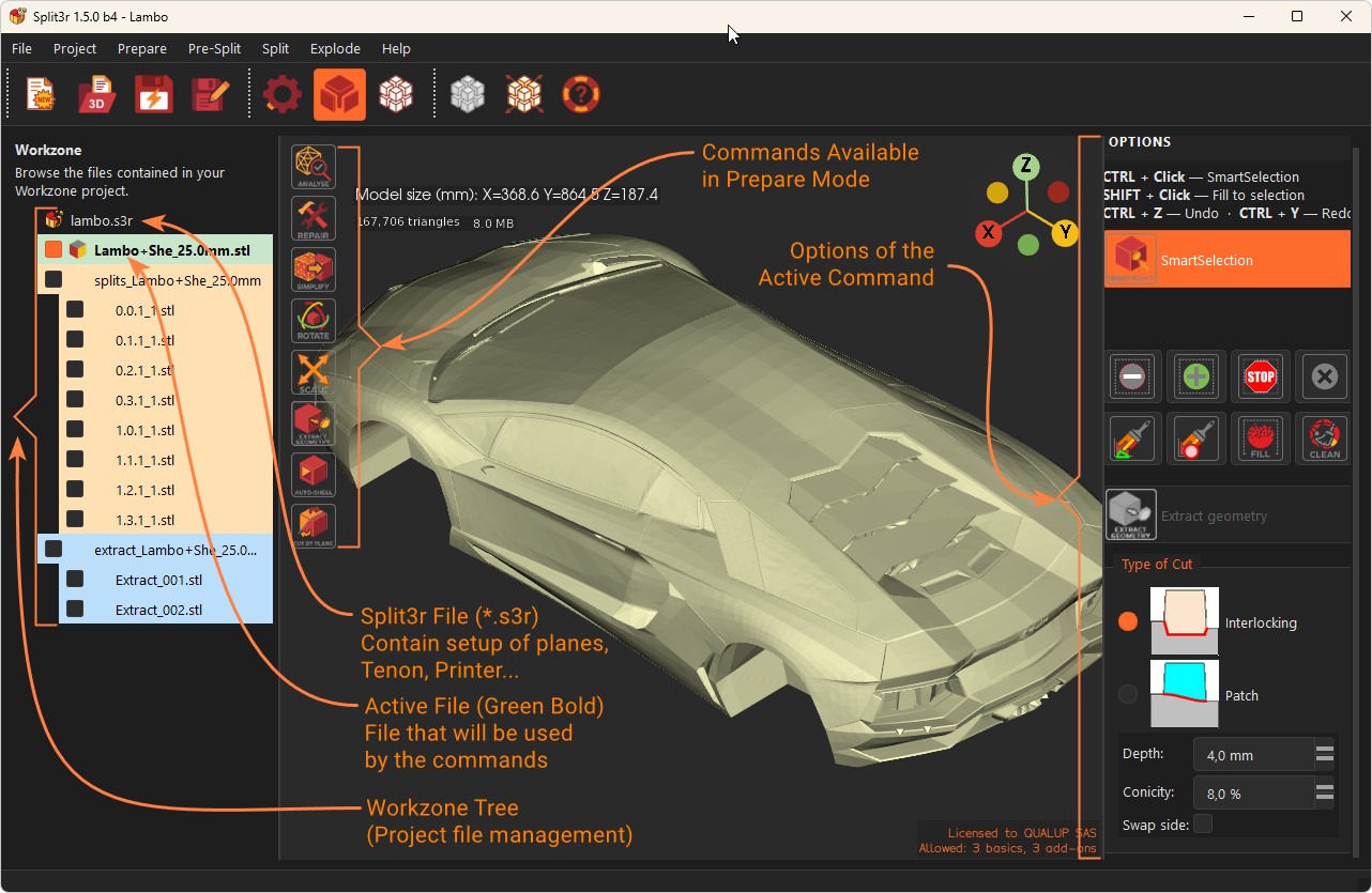
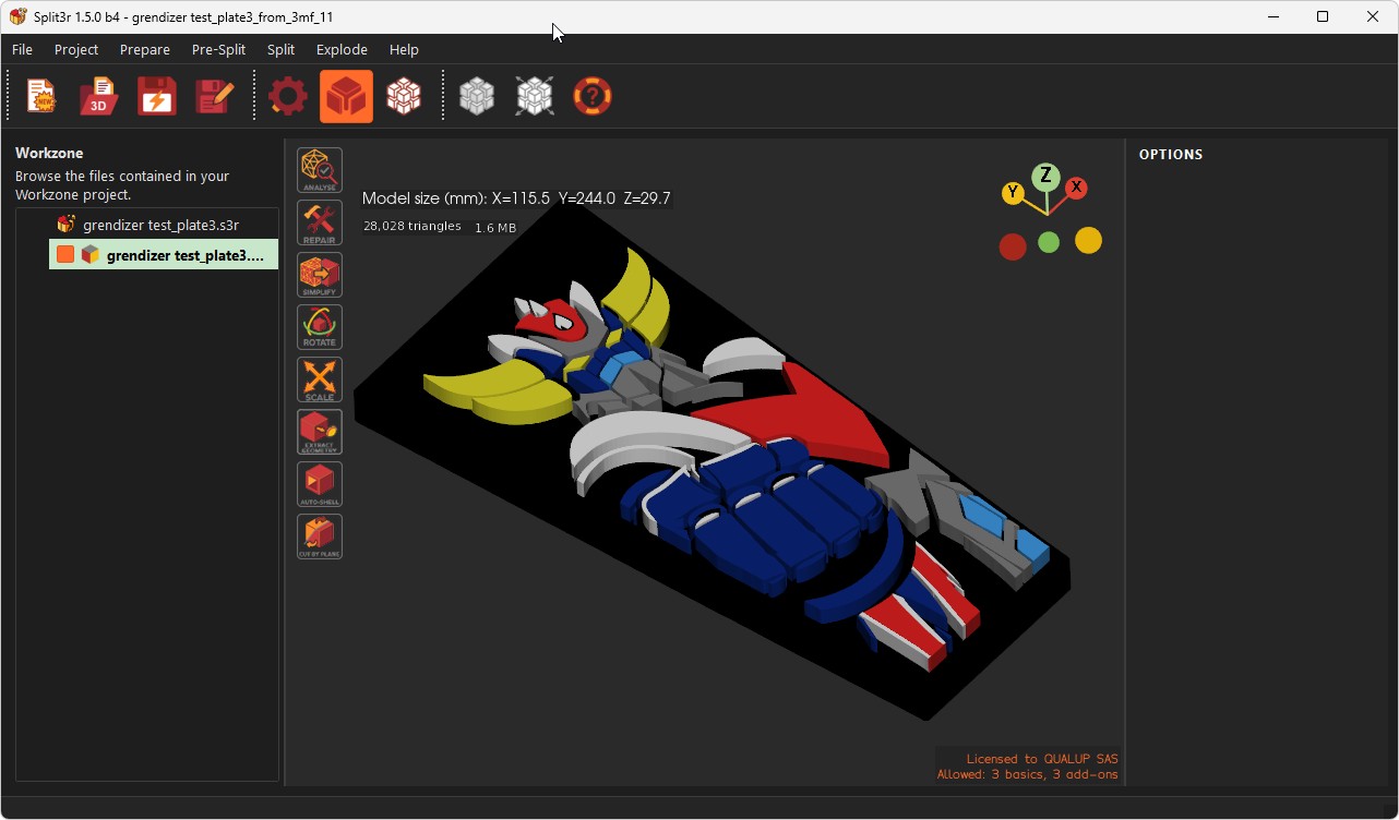
Switch between PREPARE, PRE-SPLIT, SPLIT and EXPLODE modes from the top bar. The 3D viewport shows the active model, the left panel changes per mode


PREPARE MODE

WORKZONE TREE : HOW IT WORKS


The Workzone is the main working area where all intermediate and resulting files are created and managed.


When you use Prepare or Presplit functions:

  • Repaired parts
  • Oriented parts
  • Scaled parts
  • ...

are automatically added to the Workzone.


The Workzone allows you to:

  • Visualize all generated elements related to the current project
  • Select which file or plane is active
  • Keep track of the different steps of the preparation process
  • Files created in the Workzone are linked to the original model and reflect the operations performed on it.
  • The Workzone acts as a staging area before exporting or further processing the parts.
  • ...


.s3r project file = Workzone settings.

The .s3r file stores Workzone parameters: selected printer, plane positions, UI options, and other session data for this project.


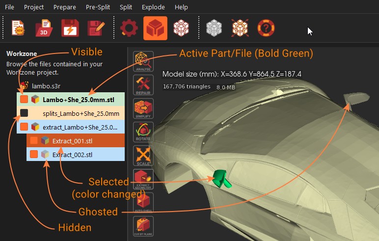
The tree is now color-coded so you can read it at a glance (<model> = your file's name):


  • Green : the active part, e.g. <model>.ply
  • Orange : Split results splits_<model>/
  • Blue : Extract results extract_<model>/
  • Violet : Cut by Plane results cut_<model>/
  • Yellow : Sort-by-color results colors_<model>/

Technical and backup folders (those starting with an underscore, like _backup_<model>/ and _export_3mf/) are hidden by default so you only see your useful parts.
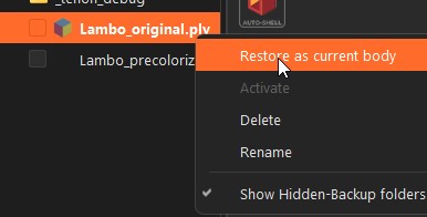
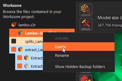
Right-click anywhere in the tree "Show Hidden-Backup folders" to reveal or hide them.
Then you can "Restore as current body" to restart and continue

(Older projects keep working, their results sit in results_<model>/, shown in orange.)


VISIBILITY LOGIC.

Checked The part/file is visible in shaded mode in the 3D view.

Each file includes a dedicated visibility icon (next to the checkbox).
This icon allows you to display parts in a semi-transparent overlay mode, making it easier to understand how pieces fit together before finalizing your cuts.

You can now act on a whole results folder at once: tick a folder's checkbox (e.g. splits_<model>/, extract_<model>/) to show all its parts in one click, or use its ghost icon to make them all semi-transparent together.


ACTIVE FILE
The Active File is the file currently used by all functions in the Prepare workspace and by the Presplit process.
The Active File is always kept at the top of the Workzone under a stable name.
Only one file can be active at a time. The Active File is displayed in Green Bold in the Workzone tree.
All operations such as Analyse, Repair, Orientation, Autoshell,... and splitting are applied to the Active File.

Before using any Prepare or Presplit function, make sure the correct file is set as active.

Activate STL
: Double clic on it in the tree or Right-click and choose Activate to make it the Active file
Only one file can be Active at a time.

DELETE


Delete
: Right-click and choose Delete to remove unneeded files/folders results from the Workzone
or hit "Del" key.
Note :
You can now delete the active part too: Split3r removes it from the 3D view and automatically loads the nearest remaining file in the same folder. Only deleting a folder that contains the active part is still blocked, switch to another part first.


IMPORTING A COLORED 3MF (BambuStudio / PrusaSlicer)

Open a 3MF with multiple bodies, multiple plates  via File  > Open or drag and drop.
Painted colors are imported from BambuStudio or PrusaSlicer. (Each slicer uses its own on-screen palette, so colors follow what's stored in the file.)
Multi-plate files: a dialog lets you pick the plate to import, with a thumbnail.
A progress bar shows the conversion

The model lands as a colored part (.ply) and keeps its colors through repair, split, extract and cut.
ANALYSE


The Reality of 3D Files


After analysing support tickets from over 2,500 users during the first six weeks of Split3r's beta release, we identified a consistent trend: over 80% of reported issues stemmed from problems inherent in the files themselves, rather than software or user error.


We all download models from popular repositories like Thingiverse, Cults3D, Printables, or Thangs... While these platforms are great resources, many uploaded files are modeled for visual purposes rather than manufacturing.

Consequently, they often carry severe geometric defects that make them unsuitable for operations like cutting or splitting.


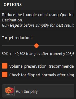
To help you identify these "dead-end" files before you waste time trying to split them, we are introducing a raw Analyze command. It doesn't modify your file, it simply exposes the truth about its geometry.

What it detects:


The tool scans for specific defects that cause boolean operations to fail:


  • Multi-Body STLs: The Blender mathematical engine we utilize cannot perform cuts on files containing multiple disconnected bodies.
  • Non-Watertight Meshes: Open edges and holes.
  • Self-Intersections: Geometry folding into itself (often invisible from the outside).
  • Multi-Body Collisions: Internal overlapping volumes that confuse slicers.
  • Non-Manifold Geometry: Mathematically impossible shapes.
  • Foldover Faces: mesh faces that are folded onto itself, like a sheet of paper bent into a “Z” shape.

Simply click on the icon, it analyses the Active file (the file displayed in Bold in the Workzone).

Before processing, Split3r pre-analyzes your STL file structure and presents options
File structure report: Shows the number of bodies detected in your file

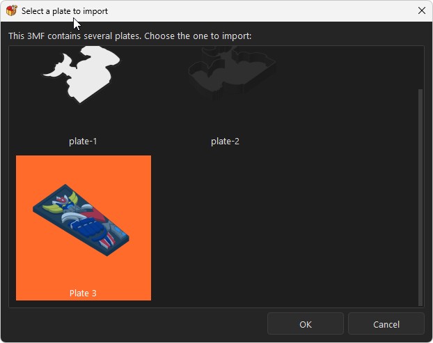
When multiple bodies are detected, choose:


  • Analyze as-is : Process the file without modifications
  • Keep largest body only : Automatically discard smaller elements (often usefull for AI generated files)
  • Keep top N bodies : Retain only the N largest bodies (generally for CAD generated files)
  • Keep all bodies : Preserve everything and create separate entries in the WorkZone (Explode everything in independant files)

Multi-body Multi-color models: "Keep all bodies & sort by color"


When you analyse a model made of several separate bodies (very common with multi-color 3MF files), Split3r asks how you want to handle them. On a colored model, one of the choices is "Keep all bodies & sort by color."
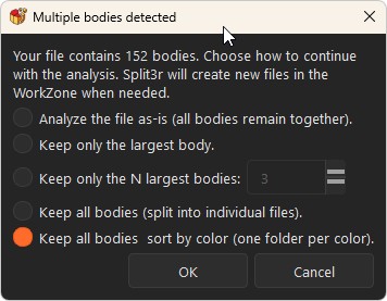
What it does:


It keeps every body, nothing is merged, and small bodies aren't discarded.

Each body is saved as its own part and filed by its dominant color.

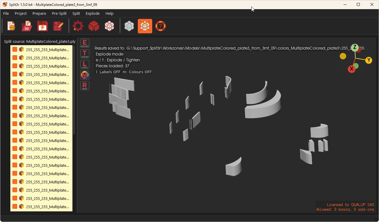
The parts land in colors_<model>/, with one sub-folder per color, named by the color's RGB value.

For example a red part goes to colors_<model>/255_0_0/, an orange one to colors_<model>/255_128_0/, and so on.

Bodies that have no color go to colors_<model>/uncolored/.

Why it's handy: before printing a multi-color model, you instantly see which parts share the same filament color, all the reds in one folder, all the blues in another, which makes sorting parts, assigning filaments and organizing your prints much easier.


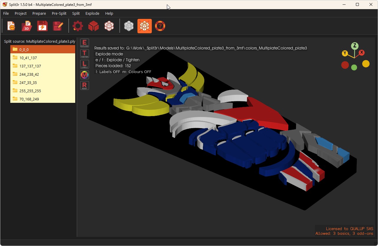
When the export finishes, Split3r switches straight to Explode so you can review all the sorted parts (and the yellow tint in the tree marks them as color-sorted results).
The Files are ready to export in 3mf and print (one click : Files > Export Workzone to colored 3mf )

REPAIR (Stable but subject to evolution)
The Repair function has been fully redesigned and now provides three distinct repair options, allowing users to choose the most appropriate strategy depending on the geometry and origin of the file.
1. Repair using standard algorithms
This option first merges internal bodies (when technically possible), then repairs common mesh issues such as self-intersections, inverted faces, holes, and duplicated or overlapping faces.
This method successfully repairs the majority of CAD generated files.

2. Repair using Split3r algorithms (organic part, AI parts and 3DScan parts)
Optimized for organic shapes and AI-generated models. This enhanced algorithm (deep repair) successfully repairs many files that other tools can't handle, making it particularly effective for AI-generated content and sculptural models.

Note: May not be optimal for mechanical/CAD files.
It is particularly effective on organic or scanned parts, but may deform some mechanical parts.

3. Repair using Blender algorithms
This option is intended as a last alternative when previous repair methods do not produce satisfactory results.
Repairs can be executed in sequence (for example, 1 followed by 2).

Repaired files are clearly identified:
Files repaired with method 1 are named R1
Files repaired with method 2 are named R2
Files repaired with method 3 are named R3

If multiple repairs are applied, file names reflect the sequence (e.g. R1-R2)

SIMPLIFY (New in version 1.4.0 - beta)
The Simplify command reduces the triangle count of a heavy STL while preserving its overall shape.
Useful on dense scans or high-poly models that slow down the slicer or Split3r itself.

Input
: Active file (e.g., Demo-Rep.stl).
Output: Demo-Rep-Sim.stl added to the Workzone.

Use cases: Lighten scanned or sculpted models, speed up slicing, reduce memory usage before AutoShell or Cut by Plane.
Open the Simplify dialog on the active file. A slider lets you choose the reduction rate, from 24% to 99%.
24%: light cleanup, geometry almost unchanged.
50
70%: good balance between size and visual fidelity for most models.
90%+: aggressive reduction, use for rough previews or very dense meshes.
Move the slider to the desired value and click OK. The simplified file is added to the Workzone with the suffix _Sim.
TIPS & NOTES
Start around 50% and decrease only if the result is still too heavy.
Simplify is non-destructive: the original file remains in the Workzone, the simplified version is a new entry.
ROTATE
The Rotate command allows you to rotate/orient your part before further operations.


Rotating the part
Rotate the model by clicking on the colored arcs:
Red: rotation around the X axis
Orange: rotation around the Y axis
Green: rotation around the Z axis

By default, the rotation is applied in 5° steps.
Hold CTRL to switch to 1° rotation steps for fine adjustments.
Hold SHIFT for free (continuous) rotation.

Validating the orientation

Click OK to confirm the orientation.
The rotated part is saved in the Workzone with the suffix _O (for oriented) added to its name.
SCALE
Scales the active model before splitting (useful to match target size or compensate for shrink).

Input: Active file (e.g., Demo-Rep.stl).
Output: Demo-Rep-Sca.stl added to the Workzone.
Modes: Percentage (%), Absolute dimension (X/Y/Z ) or Factor : eg :1.5 .
Safety: Non-destructive; creates a new step in the pipeline.
Project behavior: The current Pre-Split setup is automatically disabled before scaling,  you’ll c-onfirm the change if the scale factor is very large (> 20×).
Tip: Verify the new scaled file is Active before proceeding.

HOW IT WORKS

Input format: Enter a value with factorunit or %, so the app can compute correctly.
Percentage: 150%
Millimeters: 855mm
IMPORTANT do not forget to add mm after the value 855mm not 855
Factor (unitless): 1000 for example with a STL file stored in meters unit (leave unit empty)

Per-axis inputs (X, Y, Z): You can fill 1, 2, or 3 fields.

One value only: The other axes are computed automatically to keep proportions (no deformation). (Most common case.)

Two values: The specified axes are scaled independently; the unspecified axis does not change.
Example: X=120%, Y=130%, Z= (empty)
deform X and Y, keep Z unchanged.

Three values: The part is scaled/deformed independently on each axis using the three inputs.

Mixing units is allowed:
Example: X=120%, Y=568mm, Z=1.6 (factor)

TIPS & NOTES:

Use percent for relative growth/shrink, mm for targeting a precise dimension, or factor for quick ratios.
Very large factors (> 20×) trigger a confirmation.
After scaling, a new file (e.g., *-Sca.stl) is added to the Workzone, make sure it is Active before PRE-SPLIT.
SMARTSELECTION / EXTRACT (New in version 1.4.0 - beta)
 
The SmartSelection / Extract command lets you isolate a region of the model with a single click and extract it as a separate printable part.

Input: Active file (e.g., Demo-Rep-Sca.stl).
Output: Two new files added to the Workzone: the extracted region and the remaining body, both closed and watertight.
Use cases: Remove a feature for separate printing, split a model into logical sub-parts, isolate a damaged zone for repair, prepare multi-material or multi-color prints.

HOW IT WORKS

Click a face on the model. Split3r analyzes the surrounding geometry and automatically selects the region that makes sense to extract.

Refine the selection if needed:
Add zones: click on adjacent faces to extend the selection.
Subtract zones: remove faces you don't want to include.
Fill holes: close small gaps inside the selection.
Clean edges: smooth the selection border for a cleaner cut.
When the selection is ready, choose how to close the cut.
With Interlockig option, a live preview is displayed before extraction
.


CLOSURE OPTIONS

Interlocking: a keyed joint that allows clean reassembly of the two parts after printing. Both the joint size and the draft angle are adjustable, so you can tune the fit between the parts and make assembly easier.
Patch: a flat closure across the cut. Fast and simple. Ideal when the two parts don't need to be reassembled, or when the contact surface is mostly flat.

Click
OK to run the extraction.
Extracted parts go to extract_<model>/ (blue, named Extract_001, Extract_002…); the part you keep stays loaded under a stable name; the original and in-between versions are kept in _backup_<model>/ (hidden), so an extract is reversible.
Extend the smart selection.
Shrink the smart selection
Clear the current selection
Paint Triangle: add or remove individual triangles from the selection, hold CTRL and drag to add faces continuously, ALT and drag to erase.
Paint Sphere: add or remove every triangle contained inside a sphere. Useful for fast broad edits.
Fill: closes all holes and channels inside the selection.
Clean: removes sharp triangle spikes along the selection border for a cleaner cut
 

File “Bowser” courtesy of EON3D


TIPS & NOTES


  • CTRL+Z / CTRL+Y (Undo /Redo) are avaliable during preparation.
  • Click on the convex part for the first selection; this usually works best
  • Use Patch for permanent separations and Interlocking when the final object must be reassembled
  • Use Fill and Clean command before Extract Command
  • With interlocking mode Check the preview before extraction, the closure geometry is visible and can be adjusted without restarting the selection.


AUTOSHELL
Creates a printable shell (hollowing) on the active model with a specified wall thickness.

Input: Active file (e.g., Demo-Rep-Sca.stl).
Output: Demo-Rep-Sca-She.stl added to the Workzone.
Use cases: Reduce material, speed up print, enable lightweight parts while keeping exterior shape.

THICKNESS GUIDELINE

Note on limitations: Depending on the shell thickness you choose, the numbering of parts may no longer be possible if the shell is too weak.

Recommendation: Avoid creating shells thinner than 15 mm to preserve enough space for tenons and tolerances.

Why: Thicker shells provide reliable tenon seating, reduce breakthrough risk, and improve bonding area.

Tip: If your tenon template is large or includes fillets/chamfers, consider
18–20 mm shell thickness. Adjust tenon spacing and offsets accordingly before running Split.

Of course, avoid trying to create an autoshell on small parts that are smaller than the thickness of the shell!

VOXELS AND MODEL SIZE

AutoShell uses a voxel-based representation of the model for the internal shell.
A voxel can be seen as a 3D pixel: a small cube used to describe the volume of a part.

The voxel size defines the size of these cubes and therefore the size of the internal facets generated by the software.
Small voxels
= high precision, many internal facets, high memory usage
Large voxels
= lower precision, fewer facets, better performance

The number of voxels increases very quickly with the size of the model.
For example, a part measuring 3000 × 2000 × 1000 mm with a voxel size of 3 mm generates more than 220 million voxels, which can easily exhaust your PC’s memory.

Recommendations
The voxel size must be adapted to the overall size of the part and the power of your PC:
Parts larger than 1 meter: approximately 5–7 mm
Parts around 2 meters: approximately 10–15 mm
Using a voxel size that is too small for large parts may lead to severe slowdowns or crashes.
Always start with a larger voxel size and reduce it only if higher precision is required.

Note : This function is expected to evolve in future versions, with the introduction of an automatic voxel size adjustment based on the part dimensions, in order to improve usability and reduce the risk of excessive memory usage.
CUT BY PLANE

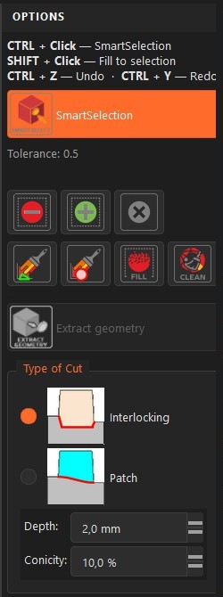
The Cut by Plane command allows you to cut the active part using the currently active cutting plane.


A dedicated 3D gizmo lets you freely position and orient the cutting plane in any direction, giving you full control over the cut location and angle.

Standard Angle and Move step are fixed to 5° - 5 mm
Shift Key disable angle and move  Step.
CTRL Key set Angle and Move step to 1° - 1 mm


Once the plane is positioned, you have two cutting options:


  • Cut All : Cuts the entire part using the active plane.
  • Cut Selected : Cuts only the selected portion of the model.

This selective cutting option helps prevent unwanted areas from being split.


When the command is executed, the system:

  • Cuts the model according to the active plane
  • Automatically adds the preselected connectors (tenons) to the cut surfaces

Connector options are available, including the possibility to add only a single tenon if required.


Cut-off pieces go to cut_<model>/ (violet, named Cut_001, Cut_002…); the part you keep stays loaded under a stable name; previous versions are kept in _backup_<model>/ (hidden), same reversible logic as Extract.


⚠️ Recommendation:

We strongly performing plane cuts before using the AutoShell function.

This approach allows you to create shells directly in the individual parts generated by Cut by Plane. In addition, the tenon geometry is automatically integrated into the AutoShell process, ensuring proper internal thickness and cleaner results.

PRE-SPLIT MODE

Position and adjust the cutting planes; use hotkeys and X/Y/Z controls to fine-tune the split configuration.

PURPOSE


PRE-SPLIT is where you configure how the model will be divided: you pick the printer constraints, define cut sizes, position the cutting planes, and (optionally) set up tenons. The resulting configuration is applied when you run Split.

1) PRINTER SELECTION


Choose the target printer profile used for this Workzone.
Sets the usable build volume (X/Y/Z) proposed in the UI.
Prevents plane positions that would generate parts larger than the printer’s capacity.
Saved in the .s3r project file so you can reopen with the same constraints.

2) CUT SIZES


Define the cut size parameters that guide how large each part can be after splitting.
Typical fields: maximum part size per axis (X, Y, Z) and optional margins.
Use these values to keep parts printable on the selected printer.
Changing cut sizes updates the recommended plane layout (you can still fine-tune manually).

3) MOVE STEP


Set the Move step (distance increment) used by the plane controls and hotkeys.
All plane moves use this step value.
Adjust it for coarse moves (large step) versus precise placement (small step).

4) MOUSE-DRIVEN PLANE ADJUSTMENT


Position cutting planes with precision:

Click the Move X, Y, or Z button
Select the plane you want to adjust
Drag to your desired position
Remaining planes automatically recalculate based on your printer dimensions

5) TENON TYPE & TEMPLATE


Configure mechanical connectors added during Split.

Type: e.g., round, rectangular, dovetail (depends on available options).

Template: a preset with dimensions/tolerances/spacing.

You can reuse your own templates; their paths are stored in the Workzone (see .s3r).

Tenons are applied at Split time; verify clearances and wall thickness first.


6) CONTROLS & HOTKEYS


Use buttons or hotkeys to place planes exactly where you want:

Buttons: X-, X+, Y-, Y+, Z-, Z+ move the active plane along the selected axis by one Move step.

Hotkeys (numpad):

X- = 4 / X+ = 6

Y- = 2 / Y+ = 8

Z- = 3 / Z+ = 9


7) TYPICAL WORKFLOW


  • Select the printer profile.
  • Set cut sizes to keep parts within the printer volume.
  • Choose the Move step.
  • Position planes with X± / Y± / Z± (or hotkeys).
  • Pick Tenon type and Template if needed.
  • Run Split to generate parts, results now go into splits_<model>/ (shown in orange). Each split makes its own folder. (Projects split with older versions still work, their results live in results_<model>/.)


NOTES & BEST PRACTICES


PRE-SPLIT always works on the Active file from PREPARE. Active the one you want.


If the EXPLODE review shows issues (misplaced planes, tiny avoidable fragments), come back to PRE-SPLIT, adjust positions/sizes/templates, then run Split again.


On low-power PCs and large meshes, prefer the buttons over holding hotkeys to avoid key repeat backlogs.

SPLIT PARTS

Split is the operation that runs after PRE-SPLIT and before you review results in EXPLODE. It takes the Active file and your current plane configuration, computes the partitions, and writes the output to a new results folder in the Workzone folder.

Input: Active file from PREPARE + plane positions from PRE-SPLIT.
Output: A folder named like results_<active-file>.stl containing the generated parts.
Non-destructive: Your original and intermediate files remain untouched, each SPLIT is attached to the active part.
Repeatable: Adjust planes and run SPLIT again.
Performance: Split time depends on mesh complexity, number of planes, and available CPU/RAM.

Best practice: Verify the correct Active file in PREPARE, then run PRESPLIT to adjust plane position

SPLIT once you’re satisfied with plane placement.


PERFORMANCE & PARALLELISM


CPU usage: The number of cores/threads used during Split depends on your PC’s capabilities and your Parameters configuration.

Check Core: By default, Split3r set to 5 threads, you can override this in Parameters if needed. Check the number of thread available and enter the maximum number of core you want ot use.

Trade-offs: More threads can speed up computation but increase RAM usage and system load. On low-RAM or thermally constrained machines, use fewer threads for stability.

Tip: Close heavy background tasks before running Split3r to avoid contention and throttling.

EXPLODE MODE

Inspect, filter, and organize the resulting parts, manage visibility and bulk actions from the parts tree.


TREE MANAGEMENT


  • Checked = Visible. The part is shown normally in the 3D view.
  • Unchecked = Hidden. The part is not rendered.
  • Ghost view icon = It appears in a semi-transparent “Ghost” display for quick inspection.

You can find the name of the part in the Workzone  tree by clicking in the 3D view.


  • You can explode any results folder you select (splits_, extract_, cut_, colors_), not only the latest split.
  • Folder checkboxes: show or ghost a whole folder's parts at once.
  • Simplified labels: Extract and Cut pieces show just their number (001, 002…).
  • Internal technical folders stay hidden.

To-check folder. Contains suspicious, very small fragments automatically filtered during Split. These usually come from model geometry that produces tiny, non-useful pieces. Review and delete if not needed.


MULTI-SELECTION & CONTEXT MENU


Multi-selection in the tree


  • Use Ctrl-click (add/remove one item) and Shift-click (range) to select multiple parts.
  • Actions apply to all selected items (e.g., Delete, Check/Uncheck).


Visibility rule with selection:


  • Checked = Visible
  • Unchecked = Hidden
  • Ghost = Ghost (semi-transparent) for quick inspection.


Right-click on a tree label


  • Right-click on the text label of any item (not just the checkbox) to open the context menu.


Menu actions (as shown bellow):


  • Delete = remove selected file(s) from the Workzone.
  • Invert folder checkboxes = flip checked/unchecked for items in the current folder.
  • Check all = check all items in the current folder.
  • Check all except selection = check everything except the currently selected items.
  • Uncheck all except selection = uncheck everything except the currently selected items.


Tip: Combine multi-selection + right-click to perform fast bulk curation (hide tiny fragments, keep only candidates, or clean a results folder).


BUTTONS & SHORTCUTS


E = Explode. Toggles/animates the exploded view to separate parts spatially for inspection.
T = Tighten. Brings parts closer together (reverse of explode) to check fit and grouping.
L = Label displays. Shows/hides labels for parts (IDs/names) to help identification.
M = Multicolor display
R = Reset to view all. Resets the camera/visibility context to show all parts clearly.

FILE STORAGE

Once processing is complete, Split3r automatically saves all generated parts inside your project’s WorkZone.


Output location

Each split creates a subfolder inside the WorkZone. The subfolder is named after the STL file used for the split, with operation tags appended.

Example: results_Lambo+Rep+Sca+She


Everything you produce is organized automatically inside your Workzone, in clearly named, color-coded folders

What you did

Folder

Color

 The part you're working on

 <model>.ply (top of Workzone)

 Green

 Split

 splits_<model>/

 Orange

 Extract

 extract_<model>/

 Blue

 Cut by Plane

cut_<model>/

 Violet

 Sort by color

 colors_<model>/

 Yellow

 Automatic backups

 _backup_<model>/

 hidden

 3MF export

 _export_3mf/

 hidden


Multiple splits per WorkZone


You can run several splits from different STL files within the same WorkZone. Each run will create its own results_<STL name + tags> subfolder, so outputs remain separated and easy to identify.
<YourWorkZone>\

    Lambo.stl

    Lambo+Rep+Sca+She.stl
    Lambo+Rep+Sca+She.s3r

    results_Lambo+Rep+Sca+She\

    0.0.0_1.stl

    0.0.0_2.stl

    ...

    results_Lambo\

    0.0.0_1.stl

    0.0.0_2.stl

    ...


Connector files (tenons) for assembly


Standard connector templates are provided here:

c:\Users\[Username]\Documents\Split3r\Tenons\...
We recommend starting with connector_flat.stl and carefully calibrating tenons (tolerances/fit) before using.


Have you found a bug ?

Send us the file via our secure server along with a complete description of how to reproduce it,

and we will take care of it and fix it.

© Copyright 2011-2026
QUALUP SAS
42, Rue du Château
71260 LUGNY - FRANCE
All Rights Reserved
Pre-sales : info@split3r.com
Technical Support : support@split3r.com
Reselling : sales@split3r.com